Successful welding has a lot to do with experience – but sometimes experience in a job can also have its disadvantages, such as if operator errors become routine or state-of-the-art welding systems are handled in the exact same way as decades-old models. And be honest now: how many welders flick through hundreds of pages of operating instructions when they switch to a new system? In this blog article, you will found out six little known facts about your welding system which you should pay attention to if you want to weld better and more efficiently.
High-quality welding systems are designed in such a way that operator errors affect them as little as possible. Experienced welders can often achieve decent results even when they completely ignore the manufacturer’s key warning notices and recommendations. But the fact remains that even the most robust welding system with the highest quality wear parts cannot be misused forever. At some point, the invoices will start rolling in – demanding sums both large and small.
If you want to use a welding system for as long and as efficiently as possible, you should know a few crucial things about it. Things that are actually obvious – and that can also be read in the operating instructions. However, as service teams in welding technology companies have found over and over again, a surprisingly large number of welders are not aware of them or simply ignore them.
So, what are the basics that you should pay attention to in order to get the most out of a modern welding system?
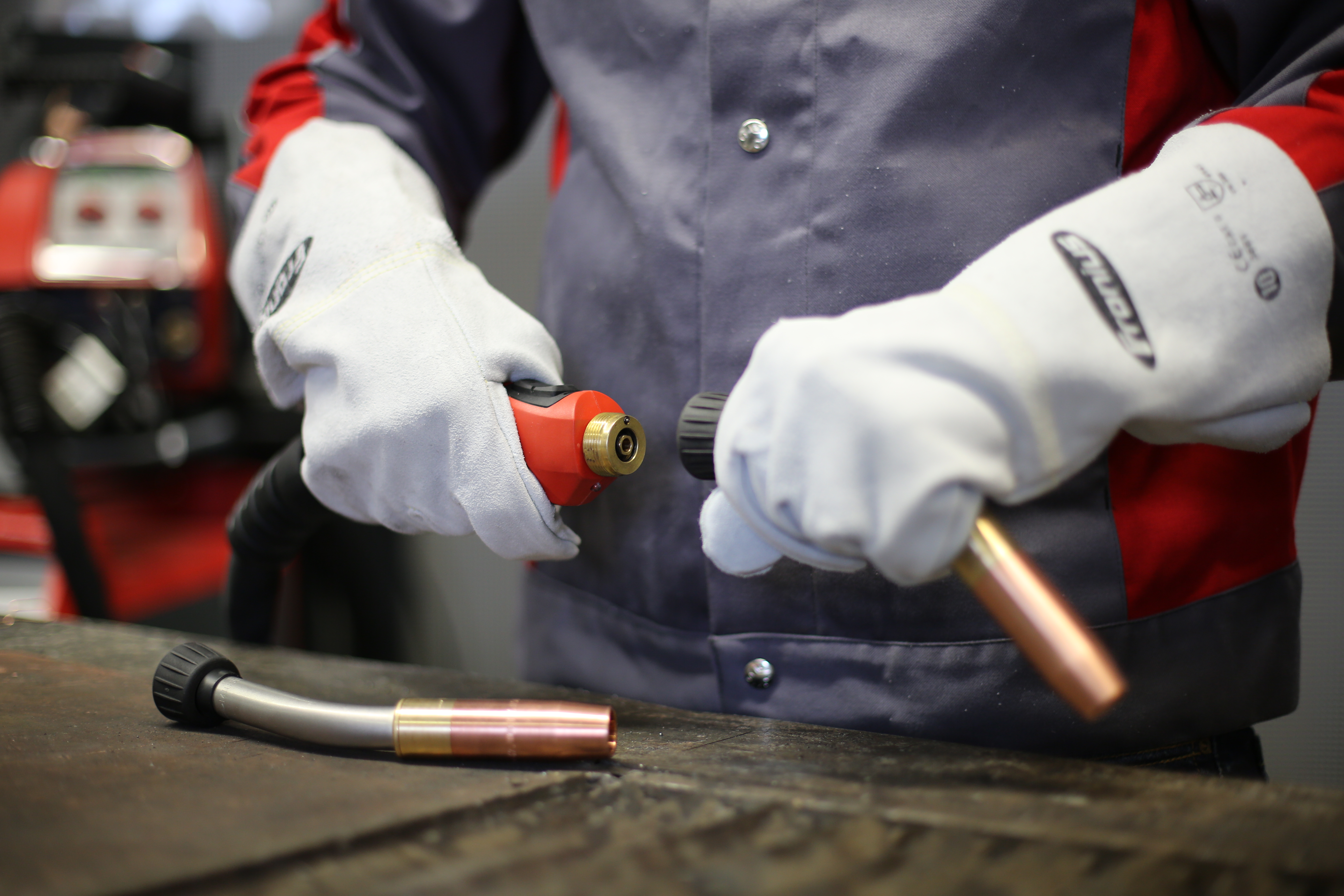
1. Match welding wire to the inner liner
State-of-the-art welding systems function best when the filler metal and the wear parts are precisely matched. One of the components this concerns is the inner liners in the hosepacks of MIG/MAG devices. Welders should therefore make sure that they always use the right inner liner for the respective welding wire: the relevant steel inner liners for steel wire and the appropriate aluminum inner liners for aluminum welding. Which inner liner is right for which welding wire can be found in the manufacturer’s specifications.
Anyone who welds aluminum with a graphite inner liner in the hosepack will not be happy in the long run. The relatively rough aluminum wire creates deposits and residues in the graphite inner liner, which also negatively affect the arc. Once the inner liner is worn through, the entire hosepack is at risk: the wire is no longer fed through the hose correctly – and it subsequently emerges from the rubber sheath. For this reason, welders should check the condition of the inner liner at regular intervals.
If different materials need to be welded at rapidly changing intervals using the same system, it is best for welders to use a universal inner liner. But the better the material of the inner liner and the welding wire are matched, the less often these wear parts need to be replaced. If a certain material is always welded, it is recommended to use the special inner liners designed for this material.
2. Choose wirefeeding rollers to suit the wire thickness
The fact that welding systems function best when wear parts and the filler metal are optimally matched to each other also applies to the interaction between wirefeeding rollers and the welding wire. This means that only the wirefeeding rollers recommended by the manufacturer for a certain wire thickness are used in the welding system.
The helps to ensure an optimum wirefeed, which has a positive effect on the stability of the arc. Even if the gaps of the feed rollers are too big or too small for the particular welding wire, in most cases, it is still conveyed. However, the wirefeeder does not function optimally under these conditions. Especially when it comes to technically complex welding processes – such as pulsing – the results often leave much to be desired.
This is partly because the proper handling of the weld pool is highly dependent on a well-functioning wirefeeder with a steady wirefeed; if the wirefeeder is working properly, many welding processes are also not optimally controlled.
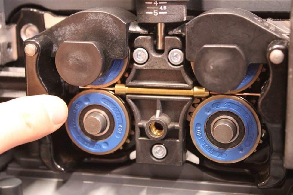
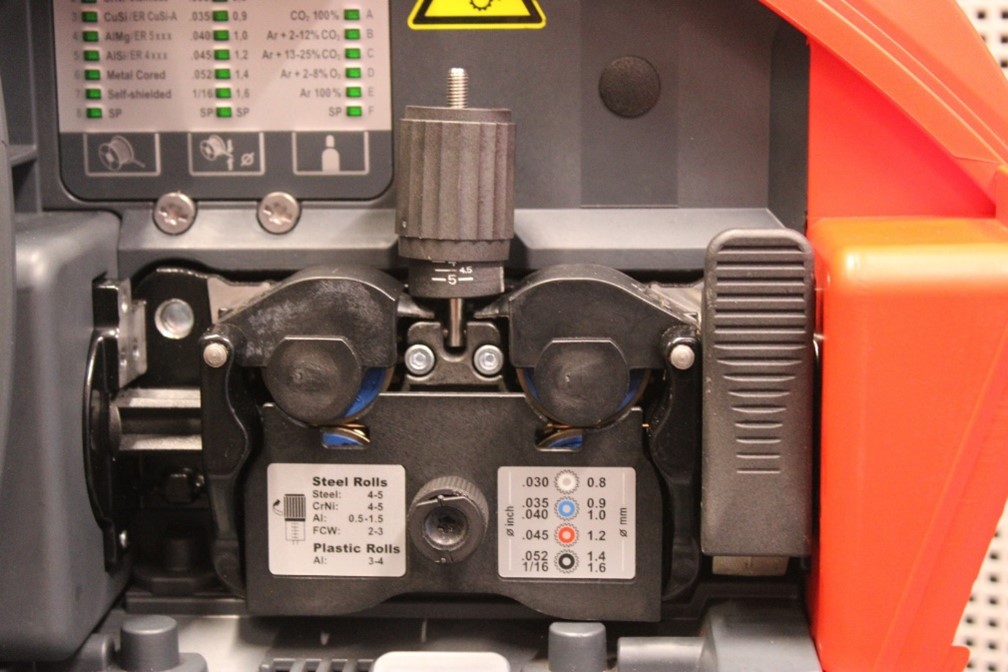
3. Contact pressure: a matter of adjustment
The right “match” between wire and wirefeeding rollers concerns not only the selection of the right components. After inserting the wirefeeding rollers recommended by the manufacturer for the corresponding welding wire into the system, the optimal contact pressure must be set. In many good welding systems, the info stickers in the area of the wirefeeding rollers provide information about how high the contact pressure should be.
Based on the manufacturer’s recommendations, fine adjustments can be made, especially as not every wire batch is the same and there can also be differences from manufacturer to manufacturer. For fine adjustments, dexterity and experience are advantageous. The wirefeeder essentially function at its best when the wirefeeding rollers firmly surround the welding wire. In this case, the operator of the welding system has 100 percent control over the wire speed.
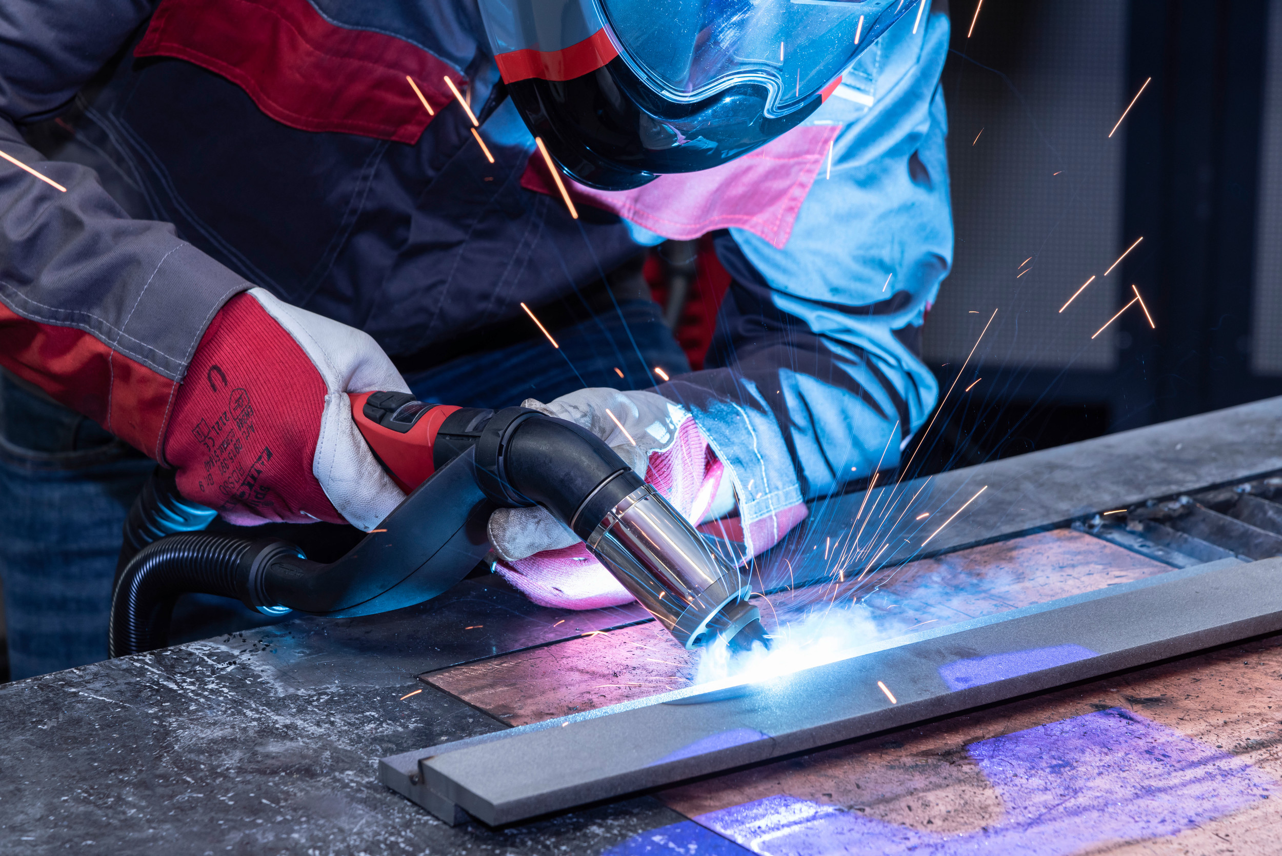
4. Optimal shielding gas flow rate
The optimal shielding gas flow rate is an important prerequisite for an arc that is as low-spatter as possible and flawless weld seams. The rule of thumb for the shielding gas flow rate on MIG/MAG welding is: wire diameter x 10. So, if a welding wire of 0.8 mm is being used, the basic recommended shielding gas flow rate is 8 liters/minute.
Another important factor which determines the shielding gas flow rate is the distance between the welding torch and the workpiece. The further apart the welding torch and the workpiece are, the more shielding gas is required for a stable arc. Based on the “wire diameter x 10” rule, individual fine adjustments must also be made here. Relevant welding experience definitely helps, since it can sometimes take a few attempts before the right shielding gas flow rate is set.
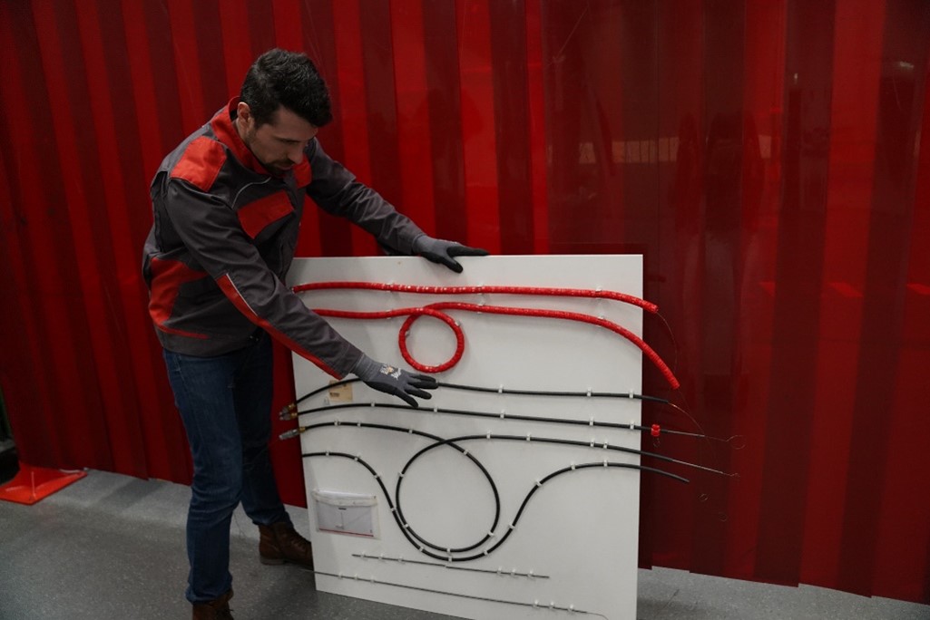
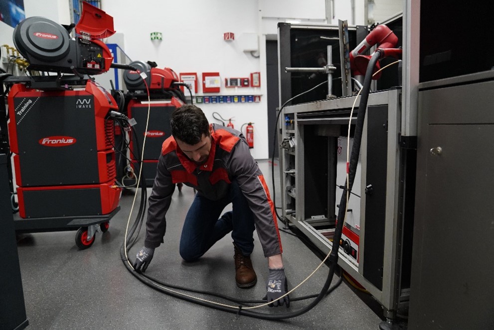
5. Align hosepack as parallel to the ground as possible
A general rule when welding is that a hosepack through which a metal wire is pushed at relatively high speed will have a high service life when it is as straight as possible.
Hosepacks for high-quality welding systems are specially designed to function without problems even with extreme windings and loops – however, the most energy-saving and resource-conserving welding is performed when the hosepack is laid out parallel to the return lead cable.
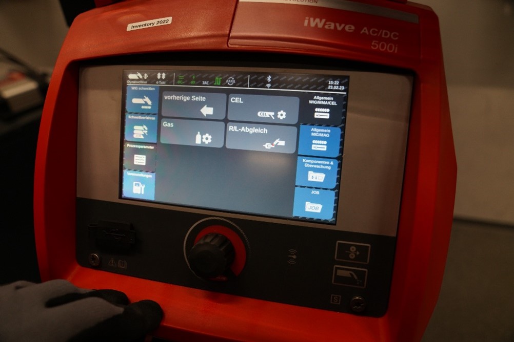
6. Calibrate ground – conduct RL adjustment
Last but not least, welding is, of course, about the right current – in other words, the flow of electrons from the negative to the positive pole. This is not the same for every welding process but rather dependent on various factors including the type of metal to be welded and the different resistances associated with it. The RL adjustment before welding therefore serves to optimally adjust the welding system to the specific circuit on site in order to compensate for errors due to any windings or loops. The letter “R” stands for the “Resistance”, “L” for the “Inductance”.
Highly sophisticated welding systems in particular can unleash their full potential with an RL adjustment before welding. An RL comparison can usually be carried out by briefly pressing a button, meaning relatively little effort is required to get the most out of a welding system – and to achieve perfect welding results.
Experience of the service teams
If something goes wrong with a modern welding system, the welding system manufacturer’s service teams are almost always consulted in the end:
“Our daily experience shows that most errors that occur with welding systems are to do with incorrect operation. Even if our systems are extremely robust in their design and use high-quality wear parts, the more closely you follow the manufacturer’s specifications and the more knowledge you have about your welding system, the better the welding results will be – and the longer the service life of the system and the wear parts”.
Patrick Bezrucka, Strategic Product Manager – Product Lines Services at Fronius
Speaking of the service life of wear parts: learn what four tips you can use to extend the storage life of contact tips and gas nozzles in this article. Check it out today!
If you have any questions about this blog post or need help with perfectly calibrating your Fronius welding system, please contact our service term using the following link. We are here for you with advice and support!
2 Comments
Ajit Kadam
4. April 2023 at 17:41good information.
Victoria Addington
22. January 2024 at 23:50I agreed when you stated that the filler metal and the wear parts must be precisely matched. My friend needs welding services for their project. I should advise him to choose a company with the right tools for the job.